9.10.2008
Stop imagining... this is what happens inside your engine.
People... everytime I am asked what happens inside a combustion chamber... I normally seek the audience to use their imagination as I explain and illustrate point by point how a 4 stroke cycle engine works.
Thanks to youtube... I finally got to see a video that actually shows in 1000's of a second - slow motion of what happens inside a running engine... particularly inside the cylinders.
You will notice how slow the burning flame is... well, thanks to HHO - this burning can go a bit faster.
8.31.2008
Slowly but Surely!

(Above is a Super 7 that experienced a thermal runaway on only 20gm. Baking Soda... see how the points are burned. But the good thing about the Super 7 is, it is not that sensitive. Once conditioned, you can reverse the polarity connections and still have no problems and even go back again to its old configuration and still work fine.)
You are now probably bombarded with the ideas that bigger is better... more is better... more LPMs', Gas flow and Bigger Bubbles is good.
I hate to burst the bubble. But contrary to what you are all led to believe.
Less is actually More! Small is actually Better! This is actually true in most and mainly on all cases. When I was first amazed with the incredible mileage gains I got from the HHO Purple Bug, I only had 0.1LPM's and no electrolytes in my system. I had a 1600 motor in the bug and it was used for racing... it normally make 6km to a liter of gas when I had this module hooked up to it, it made 12 km per liter. My unit isn't heating up, it didn't have thermal runaways nor meltdown happening.
Recently, I tried various configurations and also played with electrolytes... I was amazed with the gas production rates... but I am not impressed with the heat building up as well as the amperage rising. Definitely bad for the electrical system as well as the PVC Casing.
Again, I tried to do it with lesser electrolyte concentration... but it still went too hot. I guess, I will have to stick with less again. If it worked perfectly well the last time... then I must have been doing something right after all. Then why am I still entertaining other concepts, ways or techniques that have been problematic in the first place?
Perhaps, or maybe because I am feeling a bit competitive? I guess there really is no contest here about anything... but there is only one thing I am sure of. There is a silent race to make the world green.
The super 7 design which is my innovation... is actually an unpatented design and is also placed in open source. Though, a few examples were made and are in use. It is still a beta product. There is a challenge in casing improvement. It works passively and is designed to work on a fully saturated closed system. It also works well with an open system. The nice feature of this design is that it is a honeycomb configuration. It maximizes the usable space inside a 4" diameter circle with 7 bigger and 7 smaller tubes. The contacts are all TIG Welded for secured connections and better electrical energy flow, not to mention - Safety. It is made in a way that it allows physical extraction of HHO to be easier for engine intake Vacuum pressure.
The Super 7 builds up HHO a bit slower than all the other designs in the HHO Market since it is only designed to operate on tap water... a substitute electrolyte of a Distilled Water with a very few grams of Baking Soda can also be used. This will generate enough bubbles that are very fine. But when the vacuum extraction kicks in higher negative pressure is increased significantly and may and will also increase the amperage of the unit, the heat or thermal runaway will be way too much for the PVC casing to handle, wharfing may result which may cause water leakage.
The Super 7 draws an average of 2AMPS only... The Heat build-up is also moderate, a conditioned tube will not form muck anymore. This is a very reliable set up. This single unit is roughly equivalent to about 6 mason jars of the water4gas product using only normal tap water with very small AMPs draw.
At 0.10LPM of good quality HHO, we are certain of extracting about 1 liter of quality explosive HHO in 10 minutes or less. If this is spread over the entire use of the car in 10 minutes... we are definitely adding a liter of NOs-like gas in our operation. To use a multiple cell configuration... is to increase the LPM... I would go for this, but if I dont have enough Amps reserve in my Batteries, it will be raising a problem with faster discharging of the battery, the normal alternator charging will not be sufficient to compensate the ampere draw. But with a reliable PWM... results might be the same using a multi-cell array. For example, you want to make 1 LPM... then use a PWM (Pulse Width Motor) on your Single unit Super 7 cell... then you can get 1 LPM oh HHO; definitely, you will be getting more serious gains out of this. But again, timing is key. We need to adjust our engine timing according to the new fuel octane characteristics and of course, going back to the issue of battery discharging due to the ampere draw requirement of more cells.
But then again, If I were you, I would stick to making your first most reliable set up and use it for months first until you come to the point that you can confidently say... "It's time for an upgrade."
Better Slower but Surer... Haste makes waste.
8.25.2008
Why HHO won't work?
I am not going to attempt to convince you why HHO will work, instead - I will attempt to discourage you about HHO in this article and see if the downside will outweight the pros.
OK, now you have your kit ready... you are now ready to install.
You think that HHO is really a panacea.. an elixir... a one medicine cures all.
You are probably very careful about your car, maintaining its' originality because you are a purist. So even if your car is more than 10 years old, you probably thought you would rather retain the original paint, wheels, interior, engine rubbers hoses and lines... worse if you try keep even the original oil! OK, thats a bit too far.
The point is, you probably kept the filters clean but does not do any attempt in cleaning the carb, jettings, injectors and air passages as well as breather hoses, EGR lines, PCV's or check valves; and you probably dont ever check the air fuel ratios as well as the EGT's (Exhaust Gas Temperatures).
Clean engines does not necessarily mean, clean outside. Our Engines have arteries for liquid and gas and both needs to be flowing and all the controls must also be fully functional.
Now, you installed your kit... expecting an immediate result to kick in.
In a poorly maintained engine with a clocgged Carburetor and or Dirty Injectors, we will never be able to see any changes or immediate results even with the presence of Hydrogen or HHO. One way to check is to give sudden pressures on your gas pedal and check for any black smokes from your exhaust pipes. If there are black smokes coming out which are noticeable in volume, chances are, it won't be gone after the installation. The reason, your Jettings are too clogged or dirty that the fuel being sent inside the intake or chambers are merely bigger droplets of liquid fuel... the less atomized they are, the more harder for them to combust.
We need to remember one very important thing: Hydrogen will not ignite your gasoline or diesel, It is gasoline and diesel combustion that will cause the Hydrogen to ignite and flash or combust, The hydrogen combusting will be the one to burn the gasoline and or diesel and make them burn faster.
The above mentioned will only work if and only if, your fuel (gas or diesel) will be finely atomized or else, HHO will be useless and will never work. Even if your fuel is rich it will still ignite the HHO present in there... but if it is not atomized then it will never ever work, unless there is huge amounts of hydrogen.
HHO electrolysers are normally producing outputs of about less than a liter per minutes, if it does make more then it will have a bigger chance of creating an improvement.
For Gasoline Engines, The culprit will always be the dirty Carburetor, or the dirty injector Nozzles as well as the Engine Computer Box.
For Diesel engines, it is normally the lack of vacuum or negative pressure that is to be blamed.
Another culprit for failures is the wrong installation. HHO Electrolysers must have a relief pressure regulator as well as an intake pressure regulator. This will control the gas being sucked inside the engine. This will lead into better user control.
I believe I havent really been able to succesfully discourage you in this article about HHO. It's trully hard to unbelieve into something when in fact you already know the truth.
It's is definitely hard to unbelieve if you are already a witness and a believer.
But it is so easy to not believe in something you havent witnessed before.
And it is much easier to fear the unknown.
Nothing will always be farther than the truth.
The Question boils down to onething.
If Electrolysers can produce HHO under 3 AMPS and with only 12VDC... and these HHO gases do combust strongly... then where are these energy going?
If these bubbles explode... Then where is it going if it does not work?
8.22.2008
Hydrogen Enhancement Schematics


As you can see in the above shown diagrams or schematic illustrations... A diesel engine will have a different approach in enhancing it's air against a gasoline fed one.
Compression Ignition engines does not have a fuel mixture done in the induction stroke. However, we may mix the hydrogen gas produced on demmand with the air that enters the combustion chambers just before the power stroke occurs.
It's a lot easier to explain than to implement you know.
8.16.2008
What to do when Water gets in your engine?
This is probably the number one fear many non-mechanical vehicle owners have.
Even if you are a do it yourselfer but no actual experience in overhauling engines nor seeing open engines with different problems, then it is normal for one to fear the unknown.
For the benefit of the lay people, we will attempt to answer this fear in a laymans language many will understand.
You have successfully installed HHO or Hydrogen on Demand system in your car, then you forgot that the filler tank bubbler is not to be filled up to the rim, maybe you or some idiot did it doesn't matter.
Now, you started your engine, then it stalled. OK, some say what if pure or more hydrogen as in water itself goes in the engine, will it explode?... on the contrary, it wont and your engine will only stall.
What to do when this happens?
1. Don't Panic!
2. Remove the hose connections from the bubbler to the intake vacuum or manifold duct or to your air cleaner;
3. Remove the spark plugs (for gasoline) or glow plugs (for diesel engines) and clean them until they are dry;
4. Crank you engine while the plugs are off, for at least 20 seconds continuously one time.
5. Rest the engine for a while... you can pour or spray WD-40 in the cylinders if you wish in order to displace water and add temporary lubricity by this time;
6. Then dont wait for the WD-40 to dry up, you will need to crank the engine again for 10 seconds continuosly this time then right afterwards;
7. Replace the plugs in. Now, with the Bubbler connections still unattached, try starting your engine. It should run this time this time. As soon as it runs normally, reduce the water level of the bubbler to the right level which is somewhere in the middle or lower then reconnect the hoses.
Some misconceptions about water in your engine:
Again, it is only the lack of knowledge that creates fear inside man.
I hope I can remove this fear in just a few words... I dont believe truth comes in large packages.
Misconception about water inside the engine:
1. Water is bad inside the engine:
No way, first of all, all engine induces water everytime, it sucks air 100% all the time and air contains water vapor. You will be able to see water condensing at the end of the tail pipes every morning. And sometimes even during cold weathers. Your engine combusts air and fuel, and in the combustion process, water vapor is also produced whether you see it or smell it or not.
Water in your oil is bad, but water in oil becomes emulsified, and water mixed with your oil will not stall the engine right away, your engine will still continue to run... but you dont need to panic when this occurs. Normally, water will only mix with your oil if you overheat your engine... and while it is off and overheated, you try to put water in the radiator... This is a big NO NO!... heated engine metals can break or warf with the sudden temperature difference upon introduction of water. Just see what happens to a heated glass when dipped in water.In other words, what was described above is the fastest way to destroy your engine. So the next time you overheat it, never put water when the engine is off. Or, simply let it cool naturally and take a break while you wait for it.
Water in your engine is beneficial to keep it cool or work under the normal working temperature which is about 90 degrees centigrate. This is just below the boiling point. Water flows inside your engine and is separated by a water jacket. The water jacket are passageways inside the engine block that runs parallel to the oil passageways or main capillaries. The water constantly flows here as needed since it is controlled by a thermostat regulator normally located on the radiator cap and a water pump which is driven directly by the crankshaft either mechanically or electrically by a motor. The heated water goes to the radiator to transfer the engine heat outside and when it is cooled, it flows back again inside the engine block to keep the temperature constant and not overheat. If in such case the engine overheats due to lean fuel and air mixture or wrong ignition timing (too much advanced), the coolant reservoir unit will absorb the excess water released by the thermostat spring valve... aka Radiator Cap. Once the engine temperature subsides, this water will again return to the main system, keeping the radiator always filled up since it is a closed system.
Now that we have presented how the water benefits an engine... we can now present how it benefits the fuel combusting in your engine.
It is a known fact that you never throw water into a chemical fire, the effects can be disastrous, you need to see the video about Kitchen Fire.
Since Gasoline and Diesel or any other fuel derivatives are all considered Chemical and the fire they produce is Chemical in Nature... therefore, throwing water or adding water in this type of fire can do wonders inside the combustion chambers with the right proportion and the right condition.
We dont need to put water per se inside to achieve this wonders... air fuel mixture is about 14.7:1 therefore, only a mist or water gas is enough to aid or enhance or soupe up the existing fuel and air mixture and increase its explosive power twice as much as before. Doing this can create higher octane in your combustion chambers. Having a quick burning fuel in your cylinders will provide many benefits for the engine.
Benefits of a quick burning fuel:
1. Cleaner Combustion Chambers
2. Greatly Reduced Unburned Fuel in your Exhaust System
3. Greatly Reduced Harmful Gas Emission
4. More Power and Mechanical Efficiency to your engine
5. Reduced Engine Knocking or Pinging
6. More torque transfer directly to the wheels
7. Smoother Engine Vibration Noise
There is nothing to fear but fear itself. The secret is... everything should be balanced. All the elements of the world play in your car, engine and even your body, if we can tap the power of each of these elements... and put it in a balance... then the secret of an effortless empowering lifestyle is not beyond reach.
Handling the HHO Muck

In my experience in making and conditioning varius types of HHO or Hydrogen Electrodes/ Cells... it is unavoidable to be always in contact with the waste water or dirty water that normally occurs during the initial conditioning phase.
This however rarely occurs for clean cells... a clean cell is normally the one with lesser carbon content... or the ones that are sanded well and thoroughly.
At any rate, having direct contact with these used electrolysed water is still dangerous by any means. Although HHO emits clean H2 and O2 gases.. this doesnt mean it does not carry trace gases of Chromium Hexavalent and this is carcinogenic when inhaled. It is therefore not adviseable to be sniffing the gases emitted by your HHO electrolysers nor even touching the used water can also cause skin problems.
I have been unaware of this danger for more than a year already and has experienced skin rashes sometimes. It is therefore recomended to leave the replacement of water from your HHO to the qulified technicians, should you do it yourself... it is therefore necessary to take extreme caution and avoidance to contamination must be well observed.
Chromium Hexavalent is a byproduct from Stainless which normally is extracted from welding or electrolysis. It is treated as a waste product. But there are industrial uses for it, it is used for coating metal such as fasteners, bolts, nuts through mechanical plating.
Mechanical Plating Systems
Mechanical plating is technically equal or superior in all respects to hot dip galvanizing and electroplating.
Mechanical plating is a process where zinc, tin or other ductile metals is physically applied to metal substrates, usually steel. With thickness typically between 5 – 15 µm, Mechanical plating provides a robust surface resistant to corrosion. It utilizes impact energy to cold weld fine metal particles to the substrate. The system typically uses an open-ended barrel with glass beads as the impact medium. It provides a smooth, semi-bright finish with superior corrosion protection and does not introduce hydrogen embrittlement, making it ideal for high strength fasteners.
Hexavalent Chromium
Hexavalent chromium (Cr(VI)) compounds are a group of chemical substances that contain the metallic element chromium in its positive-6 valence (hexavalent) state. Occupational exposures to Cr(VI) occur during the production of stainless steel, chromate chemicals, and chromate pigments. Cr(VI) exposures also occur during other work activities such as stainless steel welding, thermal cutting, chrome plating, painting, and coating processes.
NIOSH considers all Cr(VI) compounds to be potential occupational carcinogens. An increased risk of lung cancer has been demonstrated in workers exposed to Cr(VI) compounds. Other adverse health effects associated with Cr(VI) exposure include dermal irritation, skin ulceration, allergic contact dermatitis, occupational asthma, nasal irritation and ulceration, perforated nasal septa, rhinitis, nosebleed, respiratory irritation, nasal cancer, sinus cancer, eye irritation and damage, perforated eardrums, kidney damage, liver damage, pulmonary congestion and edema, epigastric pain, and erosion and discoloration of the teeth.
Cr(VI) compounds vary in solubility from those that are readily soluble to those which are practically insoluble in water. In 1975 NIOSH documented the carcinogenic effects of water-insoluble Cr(VI) compounds. The NIOSH 1988 testimony to OSHA on the air contaminants standard recommended that all Cr(VI) compounds, regardless of their degree of solubility in water, be considered occupational carcinogens. NIOSH is currently reviewing and evaluating the available information on Cr(VI) compounds including the toxicology, health effects, industrial hygiene, and analytical chemistry literature in order to update its 1975 criteria document on Cr(VI).
Health Effects of Hexavalent Chromium
Hexavalent chromium is a toxic form of the element chromium. Hexavalent
chromium compounds are man-made and widely used in many different industries.
Some major industrial sources of hexavalent chromium are:
• chromate pigments in dyes, paints, inks, and plastics
• chromates added as anti-corrosive agents to paints, primers and other surface coatings
• chrome plating by depositing chromium metal onto an item’s surface using a solution of chromic acid
• particles released during smelting of ferrochromium ore
• fume from welding stainless steel or nonferrous chromium alloys
• impurity present in portland cement.
How hexavalent chromium can harm employees
Workplace exposure to hexavalent chromium may cause the following health effects:
• lung cancer in workers who breathe airborne hexavalent chromium
• irritation or damage to the nose, throat, and lung (respiratory tract) if hexavalent chromium is breathed at high levels
• irritation or damage to the eyes and skin if hexavalent chromium contacts these organs in high concentrations.
How hexavalent chromium affects the nose, throat and lungs
Breathing in high levels of hexavalent chromium can cause irritation to the nose and throat. Symptoms may include runny nose, sneezing, coughing, itching and a burning sensation. Repeated or prolonged exposure can cause sores to develop in the nose and result in nosebleeds. If the damage is severe, the nasal septum (wall separating the nasal passages) develops a hole in it (perforation). Breathing small amounts of hexavalent chromium even for long periods does not cause respiratory tract irritation in most people. Some employees become allergic to hexavalent chromium so that inhaling chromate compounds can cause asthma symptoms such as wheezing and shortness of breath.
How hexavalent chromium affects the skin
Some employees can also develop an allergic skin reaction, called allergic contact dermatitis. This occurs from handling liquids or solids containing hexavalent chromium. Once an employee becomes allergic, brief skin contact causes swelling and a red, itchy rash that becomes crusty and thickened with prolonged exposure. Allergic contact dermatitis is long lasting and more severe with repeated skin contact. Direct skin contact with hexavalent chromium can cause a non-allergic skin irritation. Contact with non-intact skin can also lead to chrome ulcers. These are small crusted skin sores with a rounded border. They heal slowly and leave scars.
How employees can be exposed to hexavalent chromium
Employees can inhale airborne hexavalent chromium as a dust, fume or mist while:
• producing chromate pigments and powders; chromic acid; chromium catalysts, dyes, and coatings
• working near chrome electroplating
• welding and hotworking stainless steel, high chrome alloys and chrome-coated metal
• applying and removing chromate-containing paints and other surface coatings.
Skin exposure can occur during direct handling of hexavalent chromium-containing solutions, coatings, and cements.
Steps OSHA has taken to protect employees from health hazards caused by hexavalent chromium
The new OSHA workplace standard requires employers to:
• limit eight-hour time-weighted average hexavalent chromium exposure in the workplace to 5 micrograms or less per cubic meter of air.
• perform periodic monitoring at least every 6 months if initial monitoring shows employee exposure at or above the action level (2.5 micrograms per cubic meter of air calculated as an 8-hour time-weighted average).
• provide appropriate personal protective clothing and equipment when there is likely to be a hazard present from skin or eye contact.
• implement good personal hygiene and housekeeping practices to prevent hexavalent chromium exposure.
• prohibit employee rotation as a method to achieve compliance with the exposure limit (PEL).
• provide respiratory protection as specified in the standard.
• make available medical examinations to employees within 30 days of initial assignment, annually, to those exposed in an emergency situation, to those who experience signs or symptoms of adverse health effects associated with hexavalent chromium exposure, to those who are or may be exposed at or above the action level for 30 or more days a year, and at termination of employment.
For more complete information:
U.S. Department of Labor
www.osha.gov
(800) 321-OSHA
DSG 7/2006
8.09.2008
Warning! Used Electrolytes is Cancerous!
Here's a dangerous substance which is contained in the waste electrolytes that we throw out of our HHO electgrolyzers... they are called Chromium Hexavalents... they are normally brown in color... this muck that we see contains this substance. I manage to pick up some materials related to this as follows:
from Wikipedia:
"Hexavalent chromium (Cr(VI)) compounds are those which contain the element chromium in the +6 oxidation state.
Chromates, which are Chromium (VI) compounds, are often used as pigments for photography, and in pyrotechnics, dyes, paints, inks, and plastics. They can also be used for stainless steel production, textile dyes, wood preservation, leather tanning, and as anti-corrosion and conversion coatings. They are used as corrosion inhibitors, but due to their high levels of toxicity they are being replaced by alternatives.
Hexavalent chromium is recognized as a human carcinogen via inhalation.[1] Workers in many different occupations are exposed to hexavalent chromium. Occupational exposures occur mainly among workers who:
* handle dry chromate-containing pigments
* spray chromate-containing paints and coatings
* operate chrome plating baths
* weld, cut or grind chromium-containing metals such as stainless steel.
Within the European Union, the use of hexavalent chromium in electronic equipment is largely prohibited by the Restriction of Hazardous Substances Directive.
Toxicity
In an organism's cells, hexavalent chromium (Cr(VI))undergoes reduction, first to metastable pentavalent chromium (Cr(V)), then to trivalent chromium (Cr(III)). Trivalent chromium binds to proteins and creates haptens which trigger immune system reaction. Once developed, chrome sensitivity becomes fairly persistent; in such cases, even contact with chromate-dyed textiles or wearing of chromate-tanned leather shoes can cause or exacerbate contact dermatitis.
Hexavalent chromium compounds are genotoxic carcinogens. Chronic inhalation of hexavalent chromium compounds increases risk of lung cancer (lungs are especially vulnerable, followed by fine capillaries in kidneys and intestine). It appears that the mechanism of genotoxicity relies on pentavalent or trivalent chromium. According to some researchers, the damage is caused by hydroxyl radicals, produced during reoxidation of pentavalent chromium by hydrogen peroxide molecules present in the cell. Zinc chromate is the strongest carcinogen of the chromates used in industry. Soluble compounds, like chromic acid, are much weaker carcinogens.[1] Chromium(III)compounds are much less toxic than Chromium(VI) compounds.
Permissible Exposure Limit (PEL or OSHA PEL)
The OSHA PEL for airborne exposures to hexavalent chromium is 5 µg/m3 (0.005 mg/m3).[2]
Reaction with Vitamin C
Researchers have recently reported discovering that vitamin C reacts inside human lung cells with chromium(VI), causing massive DNA damage. Low doses of chromium(VI), combined with vitamin C, produce up to 15 times as many chromosomal breaks and up to 10 times more mutations, compared with cells lacking vitamin C. Outside cells, vitamin C actually protects against the cellular damage caused by hexavalent chromium.[3]
Chromium(VI) and drinking water
Hexavalent chromium is the substance against which Erin Brockovich campaigned. It was found in drinking water in the Southern California town of Hinkley. Chromium(VI) is carcinogenic in groundwater,[4] and the 0.58 ppm in the groundwater in Hinkley exceeded the Maximum Contaminant Level of 0.10 ppm currently set by the United States Environmental Protection Agency.[5] A similar case was discovered in 2007 in Asopos River, near Oinofyta, Greece and Brockovich is again focusing on it. [6]"
It is therefore imperative for all HHO experimenters to be conducting safety measures in handling this harmful chemical. Specialy in disposing their electrolytes to the ground.
A Good practive would be to put them in plastic containers with a mark.... you may also filter these water for the purpose of reusing them again in your electrolysers.
HHO containers must also bear a sticker to warn users of its danger to human handling.
Always wear the necessary protection gears in handling your HHO's.
8.06.2008
The 4 Stroke Gasoline Engine
The Otto cycle
Four-stroke cycle (or Otto cycle)
Four-stroke cycle (or Otto cycle)
The Otto cycle engine was first patented by Eugenio Barsanti and Felice Matteucci in 1854 followed by a first prototype in 1860. It was also conceptualized by French engineer, Alphonse Beau de Rochas in 1862 and, independently, by the German engineer Nicolaus Otto in 1876[citation needed]. Its power cycle consists of adiabatic compression, heat addition at constant volume, adiabatic expansion and rejection of heat at constant volume, characterized by four strokes, or reciprocating movements of a piston in a cylinder:
1. intake (induction) stroke
2. compression stroke
3. power stroke
4. exhaust stroke
The cycle begins at top dead center (TDC), when the piston is furthest away from the axis of the crankshaft. On the intake or induction stroke of the piston, the piston descends from the top of the cylinder, reduces the pressure inside the cylinder. A mixture of fuel and air is forced (by atmospheric or greater pressure) into the cylinder through the intake (inlet) port. The intake (inlet) valve (or valves) then close(s), and the compression stroke compresses the fuel–air mixture. The air–fuel mixture is then ignited near the end of the compression stroke, usually by a spark plug (for a gasoline or Otto cycle engine) or by the heat and pressure of compression (for a Diesel cycle or compression ignition engine). The resulting pressure of burning gases pushes the piston through the power stroke. In the exhaust stroke, the piston pushes the products of combustion from the cylinder through an exhaust valve or valves.
Valve train
The valves are typically operated by a camshaft rotating at half the speed of the crankshaft. It has a series of cams along its length, each designed to open a valve during the appropriate part of an intake or exhaust stroke. A tappet between valve and cam is a contact surface on which the cam slides to open the valve. The location of camshafts vary among engines, as does the quantity. Many engines use one or more camshafts “above” a row (or each row) of cylinders, as in the illustration, in which each cam directly actuates a valve through a flat tappet. In other engine designs the camshaft is in the crankcase, in which case each cam contacts a push rod, which contacts a rocker arm which opens a valve. The overhead cam design typically allows higher engine speeds because it provides the most direct path between cam and valve.
Top dead center, before cycle begins 1 – Intake stroke 2 – Compression stroke
Starting position, intake stroke, and compression stroke.
Fuel ignites 3 – Power stroke 4 – Exhaust stroke
Ignition of fuel, power stroke, and exhaust stroke.
Valve clearance adjustment
This article or section contains instructions, advice, or how-to content.
The purpose of Wikipedia is to present facts, not to teach subject matter. Please help improve this article by removing or rewriting the how-to content, which may qualify for a move to Wikiversity, http://www.wikihow.com/, or http://howto.wikia.com/.
Valve clearance refers to the small gap between a valve lifter and a valve stem (or between a rocker arm and a valve stem) that ensures that the valve completely closes. On engines that require manual valve adjustment, excessive clearance will cause excessive noise from the valve train (“hammering”) during operation. Improper valve clearance reduces engine performance and increases wear and noise.
Most engines have the valve clearance set by grinding the end of the valve stem during engine assembly, overhead cams not needing subsequent adjustment. All engines with poppet-type valves make some sort of allowance for maintaining this "expansion joint", while less sophisticated engines use solid, "non-adjustable” components which are simply ground off at the contact points to provide the correct clearance (though the low efficiency of this design may not be practical when the cost of labor is very high). Another method is to provide some method of manually changing the clearance with adjustable screws or shims, the implementation of which depends on and varies widely with the design of the engine. Manual valve lash adjustment is used in almost all very high performance engines because the hydraulic adjusters used in "automatic" systems are often affected by the extreme valve train accelerations of ultra high-speed engines.
Most modern production engines use some form of automatic valve adjustment (usually hydraulic) to maintain a state known as "zero lash". In pushrod and some OHC engines this adjuster is incorporated into the tappet, lash adjuster or tip of the rocker. Many DOHC engines now employ tiny hydraulic lash adjusters in the top of the cam followers to maintain "zero lash". "Zero lash" is a desirable condition, since this allows for very quiet engine operation. Hydraulic lifters or lash adjusters also reduce required maintenance, reduce noise, help engines to perform at peak efficiency and minimize exhaust emissions by compensating for wear and expansion of various engine components. Earlier engines, mostly those with push rods and rocker arms, used adjustable tappets or hydraulic lifters to automatically compensate for valve train component and camshaft wear. Lack of valve clearance will prevent valve closure causing leakage and valve damage.
Valve clearance adjustment must be performed to manufacturer's specifications. It is normal that the exhaust valve will have a larger clearance. Adjustment is performed by either adjusting the rocker arm or placing shims between cam follower and valve stem. Most modern engines have hydraulic lifters and require only infrequent adjustment.[citation needed]
Valve clearance measurement
Valve clearance is measured with the valve closed, typically at top dead center between the compression and power strokes. The tappet will be resting on the heel of the cam lobe. A feeler gauge must pass through the clearance space. The feeler gauge should fit in and out with a slight drag. If the feeler gauge will not fit in, then the clearance is too small. If the blade of the feeler gauge fits in too loosely, the clearance is too large.
Valve clearance too wide
A too-wide valve clearance causes excessive wear of the camshaft and valve lifter contact areas, and noise. Should the clearance become wide enough, valve timing is significantly affected, resulting in poor performance.
Valve clearance too narrow
A too-narrow valve clearance does not allow for heat expansion and results in the failure of the valve to fully close. The combustion chamber does not seal properly, resulting in poor compression, which reduces performance. The valve can also overheat and even melt. However heat expansion can have the opposite effect in overhead cam engines that use aluminium alloy cylinder heads. The coefficient of expansion of aluminium alloys are approximately twice of the steel used for the valve train and this expansion can -especially in valve trains where the cam directly operates the valve- increase the the clearance.
Port flow
The output power of an engine is dependent on the ability of intake (air–fuel mixture) and exhaust matter to move quickly through valve ports, typically located in the cylinder head. To increase an engine’s output power, irregularities in the intake and exhaust paths, such as casting flaws, can be removed and, with the aid of an air flow bench, the radii of valve port turns and valve seat configuration can be modified to reduce resistance. This process is called porting, and it can be done by hand or with a CNC machine.
Output limit
The amount of power generated by a four-stroke engine is related to its speed. The speed is ultimately limited by material strength. Valves, pistons and connecting rods (where applicable) suffer severe forces and severe acceleration, and physical breakage and piston ring flutter can occur, resulting in power loss or even engine destruction. Piston ring flutter occurs are dislodged, resulting in a loss of cylinder seal and power. If an engine spins too quickly, valves cannot close quickly enough, and this can result in contact between a valve and a piston, severely damaging the engine.
Rod/stroke ratio, an important factor in engine design, is the ratio of the length of the connecting rod to the length of the crankshaft's (or piston's) stroke. An increase in the rod/stroke ratio (a longer rod, a shorter stroke or both) results in a lower piston speed. A longer rod (and consequently, higher rod/stroke ratio,) can potentially create more power, due to the fact that with a longer connecting rod, more force from the piston is delivered tangentially to the crankshaft's rotation, delivering more torque. A shorter rod/stroke ratio creates higher piston speeds, but this can be beneficial depending on other engine characteristics. Increased piston speeds can create tumble or swirl within the cylinder and reduce detonation. Increased piston speeds can also draw fuel-air mixture into the cylinder more quickly through a larger intake runner, promoting good cylinder filling.
Rod length and stroke length are independent variables. Rod length is expressed as center-to-center (c/c) length. An engine with a particular stroke can be fitted with rods of several c/c lengths by changing the piston pin location or block deck height. A rod that is longer in relation to stroke causes the piston to dwell a longer time at top dead center and causes the piston to move toward and away from TDC more slowly. Long rod engines with a particular stroke also build suction above the piston with less force, since the piston moves away from TDC more slowly. Consequently, long rod engines tend to produce a lower port air velocity, which also reduces low speed torque. Long rods place less thrust load on the cylinder walls, thus generate less parasitic drag and result in less frictional losses as engine revolutions rise. A "short rod" engine has the opposite characteristics. “The short rod exerts more force to the crank pin at any crank angle that counts i.e.--20° ATDC to 70° ATDC” (Jere Stahl [1]). Short rod engines tend develop more torque at lower engine speeds with torque and horsepower falling off quickly as engine RPM rises to high levels. Long rod engines generally produce more power due to reduced engine drag, especially as engine RPM increases. Regardless of rod length for a given stroke, the average piston speed (usually expressed in ft/s or m/s) remains the same. What changes as the rod length becomes shorter or longer in relation to the stroke, is the RATE of motion as the piston rises and falls in relation to the crankshaft. A long rod fitted to a given stroke generates less stress on the component parts due to the lower rate of acceleration away from and toward TDC. The average piston speed is the same; however, the peak piston speed is lower with long rods.
There is no "Ideal" rod to stroke ratio, however a ratio of about 2 to 1 seems to be the upper practical limit and 1.5 to 1 the lower limit in general practice. The Chevrolet 350 engine with a 3.48" stroke and a 5.7-inch (140 mm) c/c rod has a rod/stroke ratio of 1.638 to 1. The durability and longevity of this engine seems to prove that this is a “acceptable” figure for a rod/stroke ratio number. The "small block 400" used a 3.75" stroke and a rod c/c of 5.565" for a ratio of 1.484. The SB 400 was known for torque and "running out of breath" at high engine speeds. Even with large port heads and high lift camshaft, the S/B 400 ran into a "wall" of friction when engine speeds climbed above 5000 rpm. S/B 400s we also know for wearing piston skirts and cylinder walls at a faster rate than their smaller brothers. Many people that race the S/B 400 convert the engine to 5.7 or 6.0 rods to reduce the effects of the long-stroke crankshaft and lower friction within the engine. The 1967–1969 Z-28 302 engine was fitted with a 3.0" stroke crank and in some racing applications used up to a 6.0" rod, resulting in a 2 to 1 rod/stroke. The 302 Chevrolet V-8 was famous for phenomenal power in the upper RPM range while it sacrificed low speed torque to gain the high RPM power and reliability.
Honda's B16A/B16B is considered ideal in high revolution and high durability applications and it is, not coincidentally, right in between the 1.5:1 and 2:1 ratios, with a 1.75:1 ratio. Although this gives it relative low power at lower engine speeds, it also gives it a rev-happy nature that is durable beyond its factory rev limit. Some sport bikes surpass the 1.75:1 ratio, but the lower torque at less engine speed becomes evident for practical applications such as cars(where power/weight ratio is important).
A "square engine" is an engine with a bore equal to its stroke. An engine where the bore dimension is larger than the stroke is commonly known as an oversquare engine; such engines have the ability to attain higher rotational speed since the pistons do not travel as far. Conversely, an engine with a bore that is smaller than its stroke is known as an undersquare engine; such engines cannot rotate as quickly, but are able to generate more torque at lower rotational speeds.
Four-stroke cycle (or Otto cycle)
Four-stroke cycle (or Otto cycle)
The Otto cycle engine was first patented by Eugenio Barsanti and Felice Matteucci in 1854 followed by a first prototype in 1860. It was also conceptualized by French engineer, Alphonse Beau de Rochas in 1862 and, independently, by the German engineer Nicolaus Otto in 1876[citation needed]. Its power cycle consists of adiabatic compression, heat addition at constant volume, adiabatic expansion and rejection of heat at constant volume, characterized by four strokes, or reciprocating movements of a piston in a cylinder:
1. intake (induction) stroke
2. compression stroke
3. power stroke
4. exhaust stroke
The cycle begins at top dead center (TDC), when the piston is furthest away from the axis of the crankshaft. On the intake or induction stroke of the piston, the piston descends from the top of the cylinder, reduces the pressure inside the cylinder. A mixture of fuel and air is forced (by atmospheric or greater pressure) into the cylinder through the intake (inlet) port. The intake (inlet) valve (or valves) then close(s), and the compression stroke compresses the fuel–air mixture. The air–fuel mixture is then ignited near the end of the compression stroke, usually by a spark plug (for a gasoline or Otto cycle engine) or by the heat and pressure of compression (for a Diesel cycle or compression ignition engine). The resulting pressure of burning gases pushes the piston through the power stroke. In the exhaust stroke, the piston pushes the products of combustion from the cylinder through an exhaust valve or valves.
Valve train
The valves are typically operated by a camshaft rotating at half the speed of the crankshaft. It has a series of cams along its length, each designed to open a valve during the appropriate part of an intake or exhaust stroke. A tappet between valve and cam is a contact surface on which the cam slides to open the valve. The location of camshafts vary among engines, as does the quantity. Many engines use one or more camshafts “above” a row (or each row) of cylinders, as in the illustration, in which each cam directly actuates a valve through a flat tappet. In other engine designs the camshaft is in the crankcase, in which case each cam contacts a push rod, which contacts a rocker arm which opens a valve. The overhead cam design typically allows higher engine speeds because it provides the most direct path between cam and valve.
Top dead center, before cycle begins 1 – Intake stroke 2 – Compression stroke
Starting position, intake stroke, and compression stroke.
Fuel ignites 3 – Power stroke 4 – Exhaust stroke
Ignition of fuel, power stroke, and exhaust stroke.
Valve clearance adjustment
This article or section contains instructions, advice, or how-to content.
The purpose of Wikipedia is to present facts, not to teach subject matter. Please help improve this article by removing or rewriting the how-to content, which may qualify for a move to Wikiversity, http://www.wikihow.com/, or http://howto.wikia.com/.
Valve clearance refers to the small gap between a valve lifter and a valve stem (or between a rocker arm and a valve stem) that ensures that the valve completely closes. On engines that require manual valve adjustment, excessive clearance will cause excessive noise from the valve train (“hammering”) during operation. Improper valve clearance reduces engine performance and increases wear and noise.
Most engines have the valve clearance set by grinding the end of the valve stem during engine assembly, overhead cams not needing subsequent adjustment. All engines with poppet-type valves make some sort of allowance for maintaining this "expansion joint", while less sophisticated engines use solid, "non-adjustable” components which are simply ground off at the contact points to provide the correct clearance (though the low efficiency of this design may not be practical when the cost of labor is very high). Another method is to provide some method of manually changing the clearance with adjustable screws or shims, the implementation of which depends on and varies widely with the design of the engine. Manual valve lash adjustment is used in almost all very high performance engines because the hydraulic adjusters used in "automatic" systems are often affected by the extreme valve train accelerations of ultra high-speed engines.
Most modern production engines use some form of automatic valve adjustment (usually hydraulic) to maintain a state known as "zero lash". In pushrod and some OHC engines this adjuster is incorporated into the tappet, lash adjuster or tip of the rocker. Many DOHC engines now employ tiny hydraulic lash adjusters in the top of the cam followers to maintain "zero lash". "Zero lash" is a desirable condition, since this allows for very quiet engine operation. Hydraulic lifters or lash adjusters also reduce required maintenance, reduce noise, help engines to perform at peak efficiency and minimize exhaust emissions by compensating for wear and expansion of various engine components. Earlier engines, mostly those with push rods and rocker arms, used adjustable tappets or hydraulic lifters to automatically compensate for valve train component and camshaft wear. Lack of valve clearance will prevent valve closure causing leakage and valve damage.
Valve clearance adjustment must be performed to manufacturer's specifications. It is normal that the exhaust valve will have a larger clearance. Adjustment is performed by either adjusting the rocker arm or placing shims between cam follower and valve stem. Most modern engines have hydraulic lifters and require only infrequent adjustment.[citation needed]
Valve clearance measurement
Valve clearance is measured with the valve closed, typically at top dead center between the compression and power strokes. The tappet will be resting on the heel of the cam lobe. A feeler gauge must pass through the clearance space. The feeler gauge should fit in and out with a slight drag. If the feeler gauge will not fit in, then the clearance is too small. If the blade of the feeler gauge fits in too loosely, the clearance is too large.
Valve clearance too wide
A too-wide valve clearance causes excessive wear of the camshaft and valve lifter contact areas, and noise. Should the clearance become wide enough, valve timing is significantly affected, resulting in poor performance.
Valve clearance too narrow
A too-narrow valve clearance does not allow for heat expansion and results in the failure of the valve to fully close. The combustion chamber does not seal properly, resulting in poor compression, which reduces performance. The valve can also overheat and even melt. However heat expansion can have the opposite effect in overhead cam engines that use aluminium alloy cylinder heads. The coefficient of expansion of aluminium alloys are approximately twice of the steel used for the valve train and this expansion can -especially in valve trains where the cam directly operates the valve- increase the the clearance.
Port flow
The output power of an engine is dependent on the ability of intake (air–fuel mixture) and exhaust matter to move quickly through valve ports, typically located in the cylinder head. To increase an engine’s output power, irregularities in the intake and exhaust paths, such as casting flaws, can be removed and, with the aid of an air flow bench, the radii of valve port turns and valve seat configuration can be modified to reduce resistance. This process is called porting, and it can be done by hand or with a CNC machine.
Output limit
The amount of power generated by a four-stroke engine is related to its speed. The speed is ultimately limited by material strength. Valves, pistons and connecting rods (where applicable) suffer severe forces and severe acceleration, and physical breakage and piston ring flutter can occur, resulting in power loss or even engine destruction. Piston ring flutter occurs are dislodged, resulting in a loss of cylinder seal and power. If an engine spins too quickly, valves cannot close quickly enough, and this can result in contact between a valve and a piston, severely damaging the engine.
Rod/stroke ratio, an important factor in engine design, is the ratio of the length of the connecting rod to the length of the crankshaft's (or piston's) stroke. An increase in the rod/stroke ratio (a longer rod, a shorter stroke or both) results in a lower piston speed. A longer rod (and consequently, higher rod/stroke ratio,) can potentially create more power, due to the fact that with a longer connecting rod, more force from the piston is delivered tangentially to the crankshaft's rotation, delivering more torque. A shorter rod/stroke ratio creates higher piston speeds, but this can be beneficial depending on other engine characteristics. Increased piston speeds can create tumble or swirl within the cylinder and reduce detonation. Increased piston speeds can also draw fuel-air mixture into the cylinder more quickly through a larger intake runner, promoting good cylinder filling.
Rod length and stroke length are independent variables. Rod length is expressed as center-to-center (c/c) length. An engine with a particular stroke can be fitted with rods of several c/c lengths by changing the piston pin location or block deck height. A rod that is longer in relation to stroke causes the piston to dwell a longer time at top dead center and causes the piston to move toward and away from TDC more slowly. Long rod engines with a particular stroke also build suction above the piston with less force, since the piston moves away from TDC more slowly. Consequently, long rod engines tend to produce a lower port air velocity, which also reduces low speed torque. Long rods place less thrust load on the cylinder walls, thus generate less parasitic drag and result in less frictional losses as engine revolutions rise. A "short rod" engine has the opposite characteristics. “The short rod exerts more force to the crank pin at any crank angle that counts i.e.--20° ATDC to 70° ATDC” (Jere Stahl [1]). Short rod engines tend develop more torque at lower engine speeds with torque and horsepower falling off quickly as engine RPM rises to high levels. Long rod engines generally produce more power due to reduced engine drag, especially as engine RPM increases. Regardless of rod length for a given stroke, the average piston speed (usually expressed in ft/s or m/s) remains the same. What changes as the rod length becomes shorter or longer in relation to the stroke, is the RATE of motion as the piston rises and falls in relation to the crankshaft. A long rod fitted to a given stroke generates less stress on the component parts due to the lower rate of acceleration away from and toward TDC. The average piston speed is the same; however, the peak piston speed is lower with long rods.
There is no "Ideal" rod to stroke ratio, however a ratio of about 2 to 1 seems to be the upper practical limit and 1.5 to 1 the lower limit in general practice. The Chevrolet 350 engine with a 3.48" stroke and a 5.7-inch (140 mm) c/c rod has a rod/stroke ratio of 1.638 to 1. The durability and longevity of this engine seems to prove that this is a “acceptable” figure for a rod/stroke ratio number. The "small block 400" used a 3.75" stroke and a rod c/c of 5.565" for a ratio of 1.484. The SB 400 was known for torque and "running out of breath" at high engine speeds. Even with large port heads and high lift camshaft, the S/B 400 ran into a "wall" of friction when engine speeds climbed above 5000 rpm. S/B 400s we also know for wearing piston skirts and cylinder walls at a faster rate than their smaller brothers. Many people that race the S/B 400 convert the engine to 5.7 or 6.0 rods to reduce the effects of the long-stroke crankshaft and lower friction within the engine. The 1967–1969 Z-28 302 engine was fitted with a 3.0" stroke crank and in some racing applications used up to a 6.0" rod, resulting in a 2 to 1 rod/stroke. The 302 Chevrolet V-8 was famous for phenomenal power in the upper RPM range while it sacrificed low speed torque to gain the high RPM power and reliability.
Honda's B16A/B16B is considered ideal in high revolution and high durability applications and it is, not coincidentally, right in between the 1.5:1 and 2:1 ratios, with a 1.75:1 ratio. Although this gives it relative low power at lower engine speeds, it also gives it a rev-happy nature that is durable beyond its factory rev limit. Some sport bikes surpass the 1.75:1 ratio, but the lower torque at less engine speed becomes evident for practical applications such as cars(where power/weight ratio is important).
A "square engine" is an engine with a bore equal to its stroke. An engine where the bore dimension is larger than the stroke is commonly known as an oversquare engine; such engines have the ability to attain higher rotational speed since the pistons do not travel as far. Conversely, an engine with a bore that is smaller than its stroke is known as an undersquare engine; such engines cannot rotate as quickly, but are able to generate more torque at lower rotational speeds.
7.25.2008
RunYourCarOnWaterFYI.com Has Opened Its Doors
RunYourCarOnWaterFYI.com Has Opened Its Doors
New website debunks both critics and scammers concerning legitimate run your car on water technology that is being used in thousands of vehicles today.
Highland, CO, July 23, 2008 --(PR.com)-- Run Your Car on Water FYI (runyourcaronwaterfyi.com) has opened its online doors as a premier web property where one can separate fact from fiction in regard to HHO technology. Run Your Car on Water FYI compares and contrasts gasoline-powered vehicles that use HHO generators with hydrogen cars and mythical perpetual motion machines.
According to General Manager Craig Appleton, “There has been so many scams and misinformation in this field, we felt compelled to put up a website that will put the record straight. HHO technology is real, viable and is in thousands of vehicles now, saving businesses and consumers gas mileage and dollars at the pump.”
The intent of Run Your Car on Water FYI is to separate the hyperbole from the hydrogen. HHO generators are aftermarket devices one can put on one’s gasoline-powered car or diesel vehicle that uses a small amount of water, electrolyzes it, and injects the resulting HHO gas into the engine’s intake system.
The liquid H2O is transformed into HHO gas and this assists the engine to burn more cleanly and at lower temperatures, which helps to increase gas mileage. It is the mission of this website to debunk both the critics who say that run your car on water technology cannot work and the scammers who confuse HHO technology with hydrogen cars and the mythical perpetual motion water car.
The runyourcaronwaterfyi.com website talks about the Stan Meyer water car and conspiracy theories surrounding his death, the Japanese Genepax water car, Brown’s Gas and other related technology.
According to Appleton, “The reason this technology hasn’t taken off yet is because there is so much misinformation floating around that people feel they are being scammed when they come to most websites. Our intent is to legitimize this viable technology through public education.”
Run Your Car on Water FYI
Craig Appleton
909-798-2460
replyto@runyourcaronwaterfyi.com
www.runyourcaronwaterfyi.com
7.23.2008
Hydrogen Inducement Device (tm)
This is probably a breakthrough idea whose time has been long overdue.
It is unfortunate that those who have the idea, concept or solution - normally doesn't have the means to implement or execute their plans.
And even if they have a brilliant plan that they can execute... other factors comes into the picture and again, obstruct any means to implement it.
One apparent situation is the ever growing energy crisis which affect the Global scenario up to the smallest unit of the social spectrum.
For the past 30 years... Daniel Dingel and Stanley Meyer has been carving their names in the history of the Hydrogen or Water for Fuel Race.
But so many sorts of conspiracy theories have been coming out surrounding these people.
For the last 20 years, the research and development of these technologies has subsided... it was only last year (starting June 2007) where experimenters began experimenting again after Stan Meyers Patent expired.
HHO, a.k.a. Browns Gas (named after Yull Brown) who discovered it in the 18th Century, has began surfacing in the internet in a much greater degree lately since partly because of the rising petrol prices.
To date... there are probably more than 160 websites offering HHO products for direct consumers. Mostly are E-Books for DIY'ers, (do it yourselfers)... this is normal for any breakthrough technology product, since it is not totally tested by the market and since there is no certifying body to regulate the players.
At any rate, many enterprising and over enthusiastic individuals have began using many unique brand names for their product... some are really technical sounding and yet some are misnomers.
One misnomer is that 'HHO Injection'... this is a misnomer since HHO is not really injected nor forced into the system of your ICE (internal combustion engine). the right term is INDUCTION. HHO is simply introduced in into the system by the vacuum of the intake. therefore, HHO is simply induced, therefore, INDUCTION is the right word to use here.
Since Oxygen is normally produced in a normal HHO generator, we cannot simply say that we have a Hydrogen on demand gadget... therefore, HHO must be used to differentiate these units from Real Hydrogen Generators. Real Hydrogen Generators on the other hand produce 2 output gases... one pure Oxygen and one Pure Hydrogen.
However, HHO units are much easier and cheaper to produce... and moreover, HHO generators produce HHO gases that combusts a lot faster than pure Hydrogen alone. However, Hydrogen Gas in its pure state - still combust much faster than normal Gasoline... and to combine it with Gasoline will still produce about 130 Octane. And since Oxygen is already present in the atmosphere... it is not necessary to induce more volume of Oxygen anymore since it will only further enrich the AF mixture and produce a more quicker burning fuel... but too quick is not what we really need in our internal combustion machines; otherwise, we will be needing to adjust our ignition timing to a retard position.
To add: Oxygen is already present in the atmosphere, therefore, the air being sucked during a cycle... is sufficient enough for our combustion requirement.
OK... now comes the part where I am going to reveal to you the real secret; Hydrogen Inducement... that's pure Hydrogen or HH Gas.. H2 is well probably the more appropriate term.
But H2 is commonly regarded as hard to produce... and that it involves too much energy to break... but HHO have been increasingly researched and developed further that H2 production has evolved at the same time.
It is now only a matter of time when this breakthrough technology will be available in the market. Probably much sooner than we expect.
More to come... stay tuned.
.
7.22.2008
Rob Matthies interviewed in CBC Radio, Vancouver Canada.
Talks about Running your Car with Water... and explains Why water induction is not harmful to our engines.
Rob is the pioneer in running the most cheapest to operate Electric Vehicle in the world that runs on revived dead batteries.
He also lives outside the energy grid... his house is powered with solar, hydrogen, revived batteries technology.
If you wish to contact Rob about his revived battery technology for your electric vehicles... this is his number.
Rob conducts weekly seminars and solar roadshows all over Canada, raising up awareness of school children and folks about Solar Power, Revived Batteries, alternative energy including HHO, Hydrogen and Oxygen Generators for DIY or experimenters.
Courtesy of Van Gadgeteers Club, Canada. (604) 739-7717
7.16.2008
Free Hydrogen Power
Free Hydrogen is not really free... and it is not really for everyone.
The Conspiracy Theorists might have a more darker thoughts about this statement. And the Naysayers... well, they will keep saying ney or nay.
At any rate, I am writing this blog merely for the purpose of sharing information to the worthy seekers, that's you!
You probably think - there is someone out there who is actually sharing information for free!
Yes I am... and I do not intend to make this a long and uncomfortable read for you.
Don't worry, I wont be telling you what HHO, Hydrogen, Oxygen, AF Ratios, Thermodynamics, Over Unity, AMPS Draw or anything of that sort here. You probably have bombarded yourself with information in other previous readings.
The question we want to address here is... "Can we actually make our own HHO system in our cars for free?"
Well, the answer is... perhaps it's not entirely free... but you will be able to Do everything yourself!.
First things first; Materials...
We will be building a small HHO brick... small but strong. With a standard configuration of (+nn-nn+):
1. Stainless Steel 316 or 301 1mm thick plates (2" x 3" about 5 pieces) (Hand sanded, drilled with 6mm dia. holes on all 4 corners with about 10mm clearance on the edges.
2. Plastic Bolts and Nuts 4 pcs.... (6mm dia. threads 30mm in length or more) (plastic flat washers about 40 pcs. Plastic Nuts about 8 pcs.)
3. Stainless Steel wire eye terminals... (6.5mm inner diameter .5mm thk.) 3 pcs.
4. Stainless wires (if you can get one) (cut to length)
5. Stainless Steel Bolts and Nuts with flat washers and lock washers (6mm dia. 25mm) about 2 pcs. bolts and washers and 4 pcs. nuts.
6. HDPE Plastic Jar or Container... preferably cylindrical jar with threaded cap or lid. (about 4" x 4" x 8") This will serve as your electrolyser container. (Drill 2 holes for the stainless bolts and 2 holes for the Brass fittings.
(1 Center hole for the HHO Gas output fitting... and one hole near the edge for the other breather inlet fitting. and the two smaller holes for the electrodes with equidistant locations... they need to be far apart but keep a clearance of about 15mm from the edges.
7. Brass Fittings (3/16" or 1/4") 2 pcs.
8. Fuel Hose... I recommend those black rubber hose or Vacuum hoses. (cut to length)
9. Automotive Wires with Eye Terminals (number 16, cut to length)
10. Fuse holder with fuse(15 AMPS, in line type)
11. For your bubbler, you may use the plastic (HDPE) reservoir similar to your radiator coolant reservoir.
As soon as you have the above materials in your table... the next step is to build your first Home-made HHO Generator - you can actually use right away!
Please stay tuned for the next article where I will be teaching you a step by step procedure on how you can build you first HHO - Hydrogen on demand module for your car.
Please be patient... and don't blow things up just yet!
5.18.2008
5.08.2008
How I ran my Car with water
To share this information better... I was asked by friends to make a video about How I ran my car with water.
At last.. the video is already finished. It's not something done professionally... just amateur... filled with amateur enthusiasm.
The video will be available in Canada.. and will be sold for a reasonable amount just to cover our costs.
This is a product of all my experience and experiments done out of necessity.
The reason I was forced to explore HHO was due to adversity.
I started trekking this road 20 years ago... but since there was no urgency or need for this technology those days - I simply shelved it until the need to liberate oneself from the suppressive impact of our dependency to petroleum products came into the picture.
Please check out my video in youtube on the purple bug... Mileage Test Part 2... with HHO... where I made about 50% gains (3 km. to a 250ml. gasoline with HHO).
That VW consumes 250ml. per 1.5 kilometer without HHO.
This is already a big deal for me since I only used a small 3 element HHO module... not even the super 7 cell module I dream of making.
At any rate... please stay tuned as this develops.
4.27.2008
Homemade HHO Generator for your Car!
There's a growing awareness nowadays for HHO... and partly because of the rising oil prices but mainly due to the growing consciousness about Global Warming and Environment Pollution.
Many HHO or Hydrogen on demmand systems are already out and available in the market. You can buy or become a dealer and start charging clients from USD100. and above. HHO kits may comes in different varying packages. Some are more space age while others are more like things you can find in the kitchen stuff.
I created this blog basically for those who have the time and are willing to do this themselves.
The basic requirement is a good garage technology background... thats all!
FIRST THINGS FIRST:
1. You need to understand that electricity follows the path of least resistance... therefore, we do not need a big cell to produce hydrogen... since making our elements bigger - increases the resistance... which will mean that we will be needing bigger amps.
2. You need to understand that Physics also play a huge role in Hydrogen generation... therefore, once the system is attached to your car, rest assured that the untapped vacuum power existing in any internal combustion engine is there for us to use.
3. You need to understand that playing with fire is dangerous... and playing with fire from water is more dangerous... therefore, safety is always paramount.
On the succeeding posts, you will understand HHO power more... and I will provide you a glimpse into my journey towards HHO... please stay tuned to this blog as I will update it for more HHO developments for the Do it your selfers.
Subscribe to:
Posts (Atom)
Simple Schematic for Scooters/ Motor Bikes
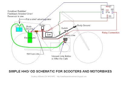
This is a very basic schematic for bikes.
HHO Chit Chat


Custom Search